
Productos
Proveedor confiable de transformadores sumergidos en aceite para proyectos energéticos globales
As a large manufactuer and exporter of oil immersed transformer in China,Cotenele have provided a large number of oil transformers for national and oversea market. Oil-immersed transformers (also known as oil-filled transformers) are among the most widely used electrical transformers in power transmission and distribution systems worldwide. As a component of critical infrastructure, this transformer is responsible for the dual tasks of boosting to reduce long-distance transmission losses and reducing voltage to meet the needs of various levels of distribution and terminal loads. It uses insulating oil as a dual medium for dielectric and cooling, and is highly favored in medium and high voltage applications, especially in terms of comprehensive advantages in reliable operation, thermal carrying capacity, and economic feasibility.All the oil immersed transformers manufactured by Cotenele comply with relevant international IEC 60076 and Chinese national standard GB/T 1094.

nuevos productos
- Sistema aislado de gas de media tensión de 33 kV
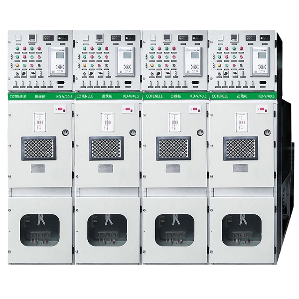
- Paneles eléctricos RMU de media tensión de 11KV
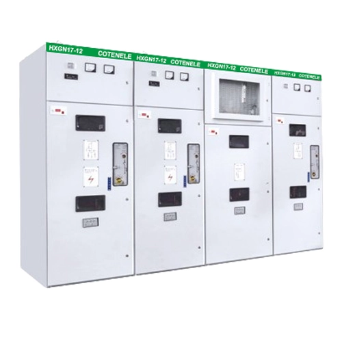
- Paneles MV de unidad principal de anillo de media tensión de 11KV
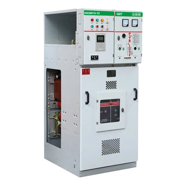
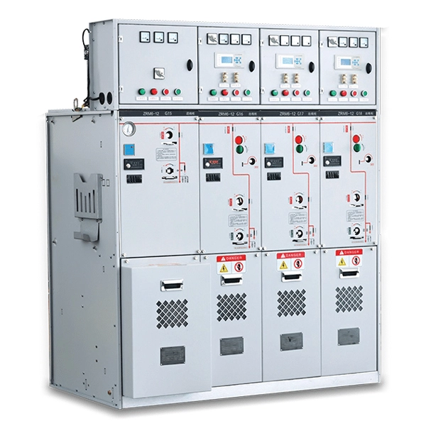
- Aparamenta de distribución aislada en gas de media tensión de 11 kV
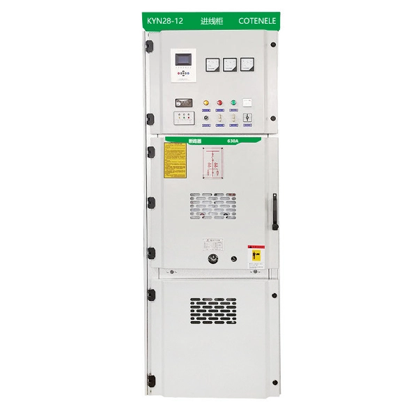
- Aparamenta de media tensión revestida de metal para interiores de 11 kV
- View as

Transformador de distribución eléctrica sumergido en aceite de 33KV
El transformador de distribución eléctrica sumergido en aceite de 33KV es uno de los principales productos de Cotenele y somos un gran fabricante y exportador de transformadores en China. Los transformadores de distribución eléctrica sumergidos en aceite de 33 kV reducen el voltaje de la red de 35 kV al voltaje del bus de bajo voltaje (generalmente 400 V) utilizado por los usuarios y son un equipo importante para conectar la red de transmisión de alto voltaje y la red de distribución de bajo voltaje. El transformador de 35 KV producido por Cotenele tiene un excelente rendimiento de aislamiento, un buen efecto de disipación de calor y un precio bajo. Es ampliamente elogiado por los clientes del mercado extranjero, especialmente en África.

Transformador eléctrico tipo sumergido en aceite de 20KV
Cotenele es un gran fabricante y exportador de transformadores eléctricos de China. A lo largo de los años, hemos proporcionado una gran cantidad de productos de transformadores eléctricos de alta calidad a clientes nacionales y extranjeros. El transformador eléctrico sumergido en aceite de 20 kV que producimos tiene una calidad confiable y un rendimiento estable, y ha recibido amplios elogios de los clientes a lo largo de los años. Todos los transformadores de potencia que producimos cumplen con estándares relevantes como IEC60076, GB/T 6451-2023, GB 1094, etc.

Transformador de potencia de distribución sumergido en aceite de 10 kV
Cotenele es un fabricante y exportador de transformadores de potencia ubicado en la "capital eléctrica de China": la ciudad de Liushi, la ciudad de Yueqing y la ciudad de Wenzhou. Nuestro transformador de potencia de distribución sumergido en aceite de 10 kV se utiliza ampliamente en el sistema de distribución de energía, como redes de distribución urbanas y rurales, empresas industriales y mineras, complejos comerciales y otros escenarios de múltiples aplicaciones.
What is an oil immersed transformer?
An oil-immersed transformer is an electrical transformer whose windings and magnetic core are submerged in a pool of insulating mineral oil (or alternative insulating fluids such as synthetic esters, natural esters, or silicone fluids). The oil in the power transformer performs two very important functions: electrical insulation and heat transfer. By surrounding the conductor windings and magnetic core, the oil increases the dielectric strength between components and removes heat generated during operation via convection and conduction to the transformer tank and external cooling surfaces。The core function of an oil transformer is to enable efficient long‑distance transmission via step‑up voltage conversion, and to satisfy distribution and end‑user needs via step‑down conversion. Owing to its large capacity, high reliability, and cost‑effectiveness, it is widely employed in power plants, transmission and distribution networks, and large industrial and mining facilities.
The technical parameters of oil immersed transformer
| Parameter | Range /Specification | ||
| Capacity range | 50 kVA-240,000 kVA(up to 500 MVA for special designs) | ||
| Rated primary voltage | 10 kV-40.5 kV | ||
| Rated secondary voltage | 0.4 kV-20KV | ||
| Frequency | 50 Hz or 60 Hz 5 | ||
| Insulation class | A(temperature resistance:105℃) | ||
| Cooling methods | ONAN/ONAF/OFAF/ODAF | ||
| Connection group | Dyn11,YNd11(customizable) | ||
| No-load loss | 0.1 kW-3.5 kW(amorphous core:0.1-1kW) | ||
| Load loss | 1.2 kW-30 kW | ||
| Short-circuit withstand capability | 63 kA-125 kA | ||
| Temperature rise limit | 55℃(standard) | ||
| Design life | ≥30 years | ||
Operation conditions
Normal Service Conditions
1. Altitude: not exceeding 1,000 m above sea level
2. Maximum ambient temperature: +40°C
3. Maximum monthly average temperature: +30°C
4. Maximum annual average temperature: +20°C
5. Minimum ambient temperature: –25°C (standard); –45°C for special designs
6. Maximum daily temperature variation: 25 K
7. Relative humidity: ≤ 90% (at 25°C ambient)
Special Service Conditions
Upon request, transformers can be engineered to accommodate special environments, including:
1. High‑altitude sites (above 1,000 m)
2. Extreme temperature ranges (–30°C to +45°C)
3. High humidity, salt‑fog, or corrosive atmospheres
4. Seismic zones
If the actual operating conditions fall outside the above normal limits, proper derating measures shall be applied in compliance with recognised standards (e.g., GB 6450).

What are the core components of an oil immersed transformer?
The Oil immersed transformers main components including bellow:
1. Core (Magnetic Circuit)
The core provides the low-reluctance magnetic path for flux linkage between primary and secondary windings. It is typically constructed from stacked grain-oriented electrical steel laminations (less than 0.35 mm thick) to minimize eddy current and hysteresis losses. Core has two main categories: core-type (where windings surround the core) and shell-type (where the core surrounds the windings).
2. Windings (Electrical Circuit)
The oil immersed power transformer windings are coils made of copper or aluminum wires arranged in the required turns ratio. They usually have two types:
Primary winding: Receives the input voltage
Secondary winding: Delivers the transformed output voltage
Small capacity low-voltage windings often use copper wires, while large capacity ones use cylindrical copper foil. The high-voltage winding is made into multiple layers of cylindrical shape, which can ensure uniform distribution of current between each turn, with small magnetic leakage, high mechanical strength, and strong short-circuit resistance.
3. Tank and Enclosure
The tank is a leak-tight steel vessel that houses the core and windings and contains the insulating oil. Tanks may be plain or fitted with corrugations and radiators to increase external surface area for cooling.
4. Insulating Oil (Transformer Oil)
Traditionally, refined mineral oil serves as the insulating and cooling medium. The oil must possess high dielectric strength, low viscosity, high flash point, and low pour point, and must be free from acids, alkalis, dust, and moisture. Alternative fluids (synthetic esters, natural esters, silicone fluids) are sometimes used for improved fire safety or biodegradability.
5. Conservator (Oil Conservator)
A conservator tank mounted above the main tank provides space for thermal expansion and contraction of the oil. It also simplifies operation by allowing monitoring of the oil level.
6. Breather
There is a silicone desiccant inside the breather to prevent water vapor from entering the transformer. Because transformer oil will expand and contract with increasing or decreasing temperature, silicone desiccant can effectively block moisture, prevent oil contamination, and also make the oil last longer.
7. Radiators
External radiator units collect heat from the oil and dissipate it to the surrounding air.
8. Bushings
Insulated fittings that provide safe connections between the high- and low-voltage windings and the external circuit. For voltages below 1 kV, porcelain bushings are used; for 10–35 kV, gas-filled or oil-filled bushings are employed; for voltages above 110 kV, capacitive bushings are required.
9. Buchholz Relay (Gas Relay)
A safety device installed in the pipe between the tank and conservator that automatically detects gas accumulation resulting from insulation failures and alerts operators to potential faults.
10. Tap Changer
A device that changes the number of turns in the winding to regulate output voltage. Tap changers are classified as on-load tap changers (OLTC) or off-load (no-load) tap changers.
11. Pressure Relief Device (Explosion Vent)
The pressure relief device is installed on the tank cover, and this safety device can release excess pressure in case of internal failure to prevent tank rupture.

Product Features
Oil-immersed transformers offer a range of distinctive features that make them the preferred choice for many applications.
| Feature | Description |
| Large Capacity Adaptability | Wide capacity range from 50 kVA to 240,000 kVA,meeting the power supply requirements of main grids and large industrial facilities |
| Efficient Heat Dissipation | Excellent thermal conductivity of insulating oil,combined withradiators or coolers,ensures low operating temperature rise and strong long-term stability |
| Cost-Effective and Durable | Mature technology,controllable manufacturing costs,longmaintenance cycles,and a design service life exceeding 30 years |
| Strong Overload Capacity | Excellent short-term overload performance,capable of handling load fluctuations during peak demand periods |
| Low Noise | The oil penetrates between lamination layers and provides acushioning effect,resulting in quieter operation |
| High Dielectric Strength | The oil provides superior insulation,increasing the dielectricstrength between components and raising the corona threshold and breakdown voltages |
| Compact Footprint | More compact than dry-type transformers for the same kVA rating |
Main Applications Scope
Oil-immersed transformers are widely deployed verious of areas:
1. Power Transmission Networks: We often see step-up transformers in power plants, as well as step-down transformers (primary voltage above 52 kV) in high/ultra-high voltage, ultra-high/high voltage, and high/medium voltage substations.
2. Power Distribution Systems: In the power distribution system, especially in various substations, distribution transformers are mainly used to reduce medium voltage (10 kV, 20 kV, 35 kV) to low voltage (400 V), providing low voltage domestic power supply for end users.
3. Industrial Facilities: Large industrial parks, mines, metallurgical bases, and manufacturing factories require stable power supply, which needs to be distributed to various applications through distribution transformers.
4. Commercial and Residential: Residential areas, commercial districts, and urban infrastructure require the use of power transformers to convert the 10KV medium voltage in the transmission system to 0.4KV for electricity and lighting.
5. Renewable Energy: In wind and solar power generation systems,need the power tansformers upper and down the voltage.
6. Railway and Transportation: Traction power supply systems also need the power distribution transformers to step-down the voltage.

The classification for the power transformers
Oil-immersed transformers can be classified according to several criteria:
1. By Number of Phases
Three-phase transformers: Most commonly used in three-phase power systems
Single-phase transformers: Used when capacity is very large and transportation constraints apply; three single-phase units may form a transformer bank
2. By Number of Windings
Two-winding transformers: The most common type, with one primary and one secondary winding
Three-winding transformers: Used for larger capacities (above 5,600 kVA) to connect three different voltage levels
3. By Core Structure
Core-type transformers: Windings surround the core; simple construction; used in most power transformers
Shell-type transformers: Core surrounds the windings; more complex construction; typically used in small dry-type transformers
4. By Enclosure Type
Non-sealed (conservator) type: Equipped with an oil conservator to accommodate oil expansion
Fully sealed type: Corrugated tank walls absorb oil expansion, eliminating the need for a conservator and preventing oil contamination from atmospheric exposure
5. By Cooling Method(as shown in the table)
| Cooling Class | Description | Application |
| ONAN | Oil Natural,Air Natural-natural oilconvection and radiator heat dissipation | Small to medium capacity,stable loads |
| ONAF | Oil Natural,Air Forced-equipped withfans for forced air cooling | Areas with significant load fluctuations;increased capacity |
| OFAF | Oil Forced,Air Forced-oil pumpcirculation with forced air cooling | Large capacity,high-load hubsubstations |
| ODAF | Oil Directed,Air Forced-directed oilflow with forced air cooling | Very large capacity transformers |
What are the difference between a ring main unit and a metal-clad switchgear?
Understanding the distinctions between oil-immersed and dry-type transformers is essential for proper selection.
| Item | Oil-Immersed Transformer | Dry-Type Transformer |
| Insulation Medium | Liquid oil(mineral oil or ester) | Solid materials (resin,varnish) |
| Cooling Medium | Oil(natural or forced circulation) | Air(natural or forced convection) |
| Visibility | Core and windings not visible(enclosed in tank) | Core and windings directly visible |
| Fire Safety | Mineral oil is flammable;esterfluids offer improved fire safety | Non-flammable,no fire risk |
| Location | Typically installed outdoors or indedicated transformer rooms | Installed indoors,often alongside switchgear |
| Overload Capacity | High thermal inertia;excellentoverload capability | Moderate;sensitive to ventilation |
| Efficiency | Very high;typically lower losses forlarge ratings | High;slightly higher losses at large ratings |
| Maintenance | Requires periodic oil testing,gasketchecks,and radiator cleaning | Low maintenance;no oil sampling;periodiccleaning only |
| Environmental Risk | Mineral oil spill risk;estermitigates impact | No liquid spill risk |
| Footprint | More compact for the same kVA | Larger footprint for the same kVA |
| Cost(Capex) | Lower per kVA for medium/high voltageratings | Higher per kVA at larger sizes |
| Bushing Type | Mostly porcelain bushings | Mostly silicone rubber bushings |

FAQS:
FAQ 1: What is service life of an oil-immersed transformer, and what factors affect it?
Usually a well-maintained oil-immersed transformer typically service life is designed to exceed 30 years. However, actual service life is influenced by several critical factors such as operating temperature (excessive heat accelerates insulation aging), moisture ingress (which degrades dielectric strength), oxygen exposure (which causes oil oxidation), loading patterns (frequent overloading shortens life), and the quality of routine maintenance including periodic oil testing and filtration. As long as the transformer operates within the rated thermal range and receives regular maintenance, it can usually achieve reliable operation for 40 to 50 years.
FAQ 2: What are the different cooling methods for oil transformation and how to choose the appropriate model?
Oil immersed transformers mainly use four cooling methods according to IEC and IEEE standards:
1. ONAN (Oil Natural, Air Natural): Relies on natural oil convection and radiator heat dissipation. Suitable for small to medium capacity transformers with stable loads.
2. ONAF (Oil Natural, Air Forced): Equipped with fans for forced air cooling, increasing the transformer's capacity. Suitable for areas with significant load fluctuations.
3. OFAF (Oil Forced, Air Forced): Uses oil pumps to circulate oil combined with forced air cooling. Suitable for large capacity transformers in high-load hub substations.
4. ODAF (Oil Directed, Air Forced): Directs oil flow through specific winding paths for optimal cooling. Used for very large capacity transformers where maximum cooling efficiency is required.
Selection depends on transformer capacity, load profile, ambient conditions, and economic considerations
FAQ 3: What are the most common faults in oil-immersed transformers, and how can they be prevented?
Common faults include:
1. Overheating: Caused by overloading, poor ventilation, or malfunctioning cooling systems. Prevention: Monitor load levels, ensure adequate ventilation, and regularly inspect cooling equipment.
2. Oil Leaks: Result from degraded gaskets, corrosion, or mechanical damage. Prevention: Regular visual inspections and timely gasket replacement.
3. Moisture Ingress: Reduces dielectric strength and accelerates oil degradation. Prevention: Maintain breather desiccant, ensure proper sealing, and perform oil testing regularly.
4. Dissolved Gas Accumulation: Indicates internal arcing, overheating, or insulation breakdown. Prevention: Install Buchholz relays for early detection and perform dissolved gas analysis (DGA) regularly.
5. Bushing Failures: Caused by contamination, cracking, or electrical stress. Prevention: Regular cleaning and inspection of bushing surfaces.
Routine maintenance including oil sampling, DGA, insulation resistance testing, and thermographic inspection is essential for early fault detection and prevention.
FAQ 4: Which standards govern the design, testing, and application of oil‑immersed transformers?
Oil‑immersed transformers must comply with a comprehensive set of international and national standards that define their electrical, mechanical, thermal, and dimensional requirements, as well as the corresponding test procedures. The principal standards applicable to these transformers include:
IEEE Standards (North America):
- IEEE C57.12.00 – Establishes general requirements for liquid‑immersed distribution, power, and regulating transformers, covering fundamental performance and construction criteria.
- IEEE C57.12.10 – Provides specific standard requirements for liquid‑immersed power transformers, addressing rating, insulation, and temperature rise limits.
- IEEE C57.129 – Sets out general requirements and test codes for oil‑immersed HVDC converter transformers, which are used in high‑voltage direct‑current transmission systems.
IEC Standards (International):
- IEC 60076 (series) – The primary international standard series for power transformers, covering general specifications, temperature rise, insulation levels, short‑circuit withstand capability, and other essential technical aspects. It serves as the global benchmark equivalent to many national standards.
Chinese National Standards (GB/T):
- GB/T 1094 (series) – The Chinese equivalent to IEC 60076, comprising multiple parts that address general requirements, temperature rise, insulation coordination, and other performance indicators.
- GB/T 6451 – Specifies the technical parameters and requirements specifically for oil‑immersed power transformers used in power systems, including rating, losses, and dimensional constraints.
These standards collectively encompass routine tests (performed on every unit), type tests (conducted on prototype designs), and special tests (such as short‑circuit or sound‑level measurements). Strict adherence to the applicable standards is mandatory to ensure transformer reliability, operational safety, and seamless interoperability within the broader power grid infrastructure.